Gains
Direct drive and low RPM
PCBMotor’s direct drive technology eliminates the need for gears and clutches and reduces the occurrence of slack errors resulting from gear wheels.
Direct drive on-board motors, therefore, can be much more accurately and easily integrated into applications than conventional motors, which significantly reduces engineering and production bill of materials.
This, combined with the PCBMotor’s low speed output (up to 120 RPM), makes it perfect for motion control systems and applications that demand superior positioning, ultra-high resolution and very fast start/stops.
No slack due to a spring-loaded rotor principle & fast start/stop actions
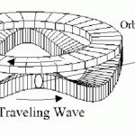
PCBMotors utilize the (patented) traveling wave principle combined with a spring-loaded rotor to generate the rotational output. This combination eliminates the occurrence of slack and play that otherwise comes from gearing mechanisms, wheels and other complicated mechanical parts.
Full holding torque – when powered-off
While stepper motors typically require constant power to maintain their holding torque and are subject to decreasing incremental torque with increasing resolution (micro-stepping), PCBMotors, on the other hand, only require power when in operation and maintain full holding torque (100%) when in power-off mode.
Superior resolution with up to 2,600,000 µpulses/revolution
Utilizing open-loop and micro-pulsing the controller, your system engineers and designers can now achieve superior micro-positioning in applications with resolutions over 2.6 million µpulses per revolution.
In 2011 PCBMotor set a technology record in an experiment using the High Resolution Twin Motor Kit with a digital position sensor, proving that ultra-high micro-pulsing is not only a reality, but a viable option.
The controller is a standard PIC18 (EEPROM) microprocessor that utilizes our own motor-interface software – programmed in C. With its rich set of structured, logical commands, the program was developed for applications to achieve their required drive patterns with precision.
It accommodates a wide range of variables for applications requiring specific:
- number of digital steps
- pulse frequency, length and intervals
- drive voltages
- and much…
A completely integrated solution (motor, drivers and electronics)
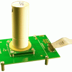
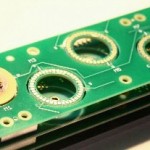
At the core of the PCBMotor are surface-mounted piezoelectric components which are mounted like all other electronic components. All electronics can, therefore, be located on the same printed circuit board, which significantly reduces the overall size the space required by applications.
Also, by surface mounting actuator components directly onto the PCB, there are no additional assembly costs for screws, wires, connectors and manual mounting. This also means an improvement to the application’s overall height and size.
If your end-product’s dimensions require a more innovative, compact design, PCBMotor’s unique form factor gives system designers greater flexibility and freedom to customize and design movement into applications/products.
The unique, hollow and ultra-slim form factor enables designers, engineers and project managers to further reduce application dimensions (size, space, weight, and height).
On top of this, every element in a PCBMotor is surface mounted (SMDs), where a standard size
20 mm stator can be mounted in only 4 seconds, by standard pick and place machines.
This means that other electronics components such as a position sensor also will be cost effective to implement.
Prev Executive Summary


