The basic elements are a:
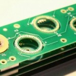
| 1. Code wheel on the rotor. The rotors on our demo PCBMotors are made from standard PCB material – the code wheel pattern is an etched Cu-layer. |  |
| 2. Optical reflective switch that sends light towards the code wheel and senses reflected light pulses. The demo kits use the reflective optical switch QRE1113GR. |  |
| 3. Software that converts sensor output into actual position and controls the driver. | . |
The actual implementation will depend on the requirements of specific application.
Absolute positioning can be achieved by adding an index track to the code wheel and letting the software count the increments to calculate the position. Alternatively a multi-track code wheel can be used for absolute position reading in any position.
If the application requires absolute positioning over more than one revolution other application dependent measures are required. If the motor is, for example, pulling a filter tuning spindle, an absolute reference position could be when the spindle is moved to its end-stop position. The end-stop position must mechanically be well defined.


