
The USB chip has 4 CMOS inputs (CTS, DSR, RI CD) and one CMOS output (RTS) that can be controlled independently of the motor. These lines are available at the edge of the driver board as small test pads and with care it is possible to solder wires to these lines although it is not recommended for production.
The driver can handle two external motors, m3 and m4, and if you only use one motor you have one ADC input free as well as the PWM output that drives the sensor LED. So you can do a sequence like shown below, but you have to wait for motor 3 to finish its movement before you can change to “motor 4”:
- m3 Select motor 3
- step66 Move 66 steps CW
- m4 Select the unused motor 4
- a4 Measure voltage on motor 4 sensor pin (0-5V)
- l180 Set LED for motor 4 to 180/255*5V
- a4 Measure again
- m3 Return to motor 3
….
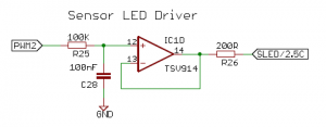
As you can see from the schematic below the PWM output is filtered and used as an ADC output. The 200R resistor is shared between the motors, but could be decreased if an additional resistor is placed in series with the sensor LED. The A4 input and SLED are both available in the 16 wire ribbon cable from the controller to the motor as well as 5V and GND and an open collector output SGND4 which is pulled low when motor 4 is selected.
PCBMotor Sensor LED Driver for High Resolution controller

PCBMotor Sensor LED Driver _ 2 for High Resolution Controller


")


