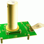
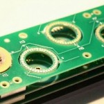
PCBMotors consist of two parts: The Stator, which holds the actuators and electrical connecting circuit; and The Rotor, which is pressed onto the surface of the stator and delivers the mechanical output.
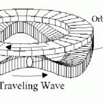
A traveling wave is generated over the stator surface, acting like a flexible ring to produce elliptical motion on the rotor interface. The elliptical motion of the contact surface propels the rotor and the connected drive-shaft. The teeth attached to the stator can be used to increase rotational speed. Operation depends on friction between the moving rotor and stator as well as amplitude and quality of the wave traveling on the stator.


