Chapter 2 Stator Manufacturing
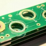
Stators are manufactured using standardized methods from the electronics industry. The piezo components are simply another set of electronic components added to the library in the layout tool. All that’s required to produce the stator is some additional milling for the stator ring.
The surface mounting of the piezo components (SMD’s) is also a standardized and fully-automated process.
For low volume series, the piezo components are supplied as Tape & Reel which fit standard Pick & Place machinery. This is a flexible and efficient solution for changes in the supply chain.
For high volume applications, a dedicated production line mounted with sorting and feeding equipment is also an option instead of Tape & Reels.
Control Driver Electronics
The motor resonates at approximately 45kHz – supplied by a 5V power supply. It generates a two-phase sinusoidal wave that is stepped up through two transformers to a drive voltage of 100-200 Vrms.
The Vs-supply for the motor can be adjusted for optimum motor speed. However, when the rotor is mounted on the stator, a minimum drive voltage is required to overcome the static friction between rotor and stator and start the motor turning.
There is a 90 degree angle of difference between the phases. Since the resonance is slightly dependent on the temperature of the PCB, the driver frequency control should take this into account. One solution is to measure the DC supply current to the motor driver.
The motor resonance frequency is primarily determined by the mechanical constants of the PCB-material and it’s necessary to compensate for the change in resonance frequency to optimize performance over the entire temperature range.
For optimal performance, the tracking feature implemented in all kits (except the Test Kit) is an effective way of setting the optimum frequency to compensate for the motor’s self-heating. The frequency tracking feature can be easily implemented in your own microcontroller.
Tracking Controller
The tracking controller, PIC16F684, is a microcontroller-based extension to our standard driver. The controller adjusts the frequency for maximum current, which gives optimum performance in the motor regardless of temperature and voltage.
When power is applied, the controller turns on the motor and makes an initial frequency sweep to find/store the resonance frequency. The motor is then stopped. The next time the motor is started manually, the stored frequency is used and optimized while the motor is running. When stopped, the last frequency is stored.
We‘ve included some features in our new tracking controller to locate the resonance on the fly while “spinning” the motor up.
The red curve in the above diagram shows the current consumption of the motor.
When the motor is started, the controller will follow the Sw1a-Sw1b arrows until the maximum current is found. Then tracking will start and follow the resonance frequency versus changes in temperature and voltage.
By properly setting the parameters, the Sw1a-b process takes a fraction of a second. In practice, it operates as a “soft” start of the movement.


