
Chapter 1 Technical Details
The block diagram below (Figure 1) shows an example Printed Circuit Board (PCB) containing stator, controller, driver and customer application electronics – all on the same PCB.
The PCBMotor system consists of the following
- PCB mounted with piezo components which acts as the stator/resonator (Patented)
- Application-specific rotor mounted on top of the stator
- Driver, sensor and motor built as a very compact unit with the electronics placed on a separate PCB (see Figure 1)
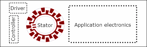
Figure 1 – Integrating electronics and mechanics
How it works
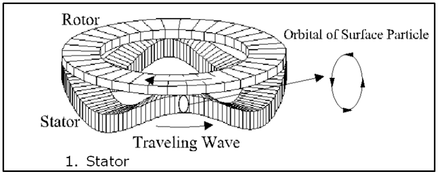
PCBMotors use the traveling wave principle to create the motion in the stator (see Figure 2).
- The stator, made from the PCB itself, holds the actuators (piezo components) and electrical connecting circuit. The PCB can also hold the driver.
- The application rotor, pressed onto the surface of the stator, delivers the mechanical output. A traveling wave is generated over the stator surface, acting as a flexible ring to produce elliptical motion on the rotor interface. The elliptical motion of the contact surface propels the rotor and the connected drive-shaft.
Elements of the Stator
Printed Circuit Board
The PCB used for a PCBMotor is made of standard FR4 material and can be from one to multiple layers depending on the application’s requirements. Manufacturing processes are well known and most PCB manufacturers can deliver to well-defined specifications.
Piezo Ceramics – commercially used since World War II
If you’ve never heard of piezos before, you might think they’re something new and exotic. In fact, piezo ceramics have been around for decades; they were actually invented during World War II. The most interesting characteristic of a piezo ceramic component is that it acts as a transducer, transforming electrical energy into mechanical energy – expanding in one dimension and contracting in another.
Today, piezo ceramics are used in many shapes and forms and in many applications: cars, cell phones, sonars, PCs, PDAs, positioning applications, cameras, medical, audio and countless others. In other words, piezo ceramics are mainstream materials.
Mechanical characteristics

Figure 3 – 30mm stator ring (left) and 6-wave stator model
PCBMotors use the traveling wave principle to create motion in the stator.
Figure 3 (right), illustrates a mode shape for a 6-wave stator – a 30 mm diameter, FR4 material stator with 48 piezo elements on each side.
The motor is driven by resonance from the mechanical system. The driver generates a 2-phase voltage that matches the resonance frequency in the stator (mechanical system).
The resonance is determined by the stiffness of the PCB material, the motor’s diameter, the thickness of the PCB, and the size and location of the piezo components mounted onto the PCB.
While it looks easy it’s not simple
On the surface it might seem like designing a stator is simple. In fact, it’s actually a very complex process and with many parameters that need to be taken into consideration to achieve the best resonance frequency.
Parameters such as:
- materials
- physical dimensions
- size
- thickness
- ring width
- piezo component placement
- bridge length
- shape and form
The optimization of these parameters goes far beyond any standard layout tools and is the reason why PCBMotor can swiftly deliver and expedite the required layouts for your applications.
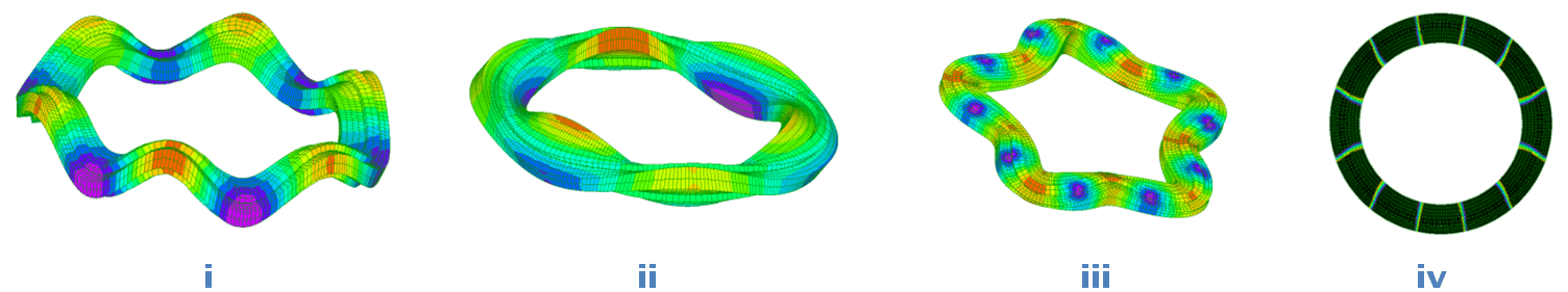
Figure 4 – Traveling wave principle at different frequencies 1 to 3, 4th is sand pattern for good resonance frequency.
Figure 4.i (above) shows a traveling wave with good resonance, 4.ii & 4.iii show a non-working traveling wave where the Eigen frequency is close to a good/working resonance. Finally 4.iv, to the right, shows the sand patterns of a standing wave with a good/working frequency.
Use our engineering expertise and customized design tools
Electrical characteristics of piezo components used in the PCBMotor
The performance of the motor (such as speed & stall torque) is closely related to the total DC current supplied to the output stage transformers. The optimum frequency can be determined by measuring the supply current as a function of frequency.
Figure 5 (below) compares the current measurements for two ordinary 330 pF capacitors (one for each phase) with a free stator (also approximately 330 pF).
The current measurement for the two capacitors shows the expected minimum at the electrical resonance of the output stage, while the free stator (with the piezo elements) has a peak at the same frequency. This behavior is due to the mechanical resonance of the stator with the piezo elements. The peak represents the quality of the mechanical resonance.
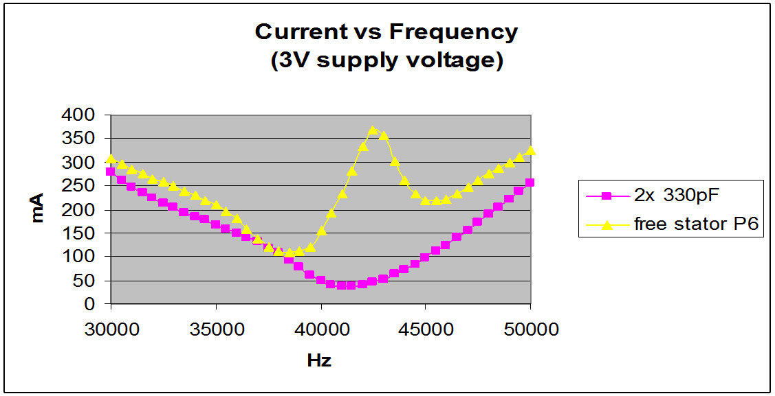
Figure 5 – Current vs. Frequency
The curves above illustrate a power efficiency of approximately 85% in the driver alone, as the 2 x 330pF current shows the loss involved in driving the stator.
The mechanical resonance varies with temperature, self-heating and operational lifetime etc., and the electrical driver needs to match the mechanical resonance for optimal performance. See also the Tracking controller section below.
Note: The overall efficiency, from electrical input to power, on the shaft of the motor is in the range of 5-10%.
prev Executive Summary


")


