Chapter 4 Key Features
Direct drive, low RPM without any slack
PCBMotor’s direct drive technology eliminates the need for gears and clutches and reduces the occurrence of slack errors resulting from gear wheels. Direct drive on-board motors, therefore, can be more accurately (and easily) integrated into applications than conventional motors, which significantly reduces engineering and production bill of materials.
This, combined with the PCBMotor’s low speed output (up to 120 RPM), makes it perfect for motion control systems and applications that demand superior positioning, ultra-high resolution and very fast start/stop actions.
Full holding torque without power
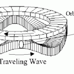
PCBMotors utilize the traveling wave principle combined with a spring-loaded rotor to generate the rotational output. PCBMotors only require power when in operation and maintain full holding torque (100%) when in power-off mode which ensures that the motor holds its position.
Infinite resolution
The ultra-high resolution of the PCBMotor is only limited by the controller and the actual load of the motor.
In 2011 PCBMotor set a technology record of 2.6 million steps per revolution using the High Resolution Twin Motor Kit with a digital position sensor, proving that ultra-high micro pulsing is not only a reality, but a viable option.
A fully-integrated solution
Motor, drivers & electronics all in one place
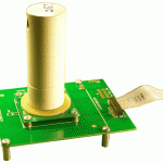
At the core of the PCBMotor is surface-mounted piezoelectric components mounted like any other electronic component. All electronics can, therefore, be located on the same printed circuit board, which significantly reduces the overall size and space required by applications.
Also, by surface mounting actuator components directly onto the PCB, there are no additional assembly costs for screws, wires, connectors and manual mounting. This also means an improvement to the application’s overall height and size, and a significant reduction to the bill of materials, and assembly time.
Design freedom
If your end-product’s dimensions require a more innovative, compact design, PCBMotor’s unique form factor gives system designers greater flexibility and the freedom to customize and design movement into their applications & products.
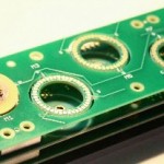
The unique, hollow, ultra-slim form factor enables designers, engineers and product managers to further reduce application dimensions (size, space, weight, and height).
The motor’s ring shape has a number of advantages. For instance, you can place a lens in the center of the motor and turn the motor to focus the lens.
See our hollow center motors (through-hole devices) & other customized designs online…
Motor Sizes, Speed and Output Power
The diameter of the motor can vary. The standard range is from 20–90mm.
A powerful motor requires a large diameter, because more piezos generate more power. However, with a longer distance to travel, speed is reduced. High speed can be obtained with a smaller diameter.
Torque and Speed vs. Motor Current
Figure 15 (right) shows the relationship between speed and torque, and the resulting output power for a Ø30mm stator.
It gives a free speed of approximately 2 rev/sec with no torque, and a stall torque of approximately 25Nmm – depending on the spring load of the motor.
Figure 16 (right) highlights the relationship between speed and torque at different current settings with thesame spring load.
Stall torque vs. temperature

Figure 17 – Stall torque versus temperature
Figure 17 (right) shows the relationship of mean stall torque and current consumption over a temperature range of +20-70 °C.
The drop in torque can be offset with an adjustment to the voltage supply.
An operating temperature range of -40-85 °C has been tested and confirmed in some customers’ applications.
Lifetime test
The PCBMotor is a friction motor. It is the friction layer that determines the lifetime.
Applications that require high torque (and force) have, in generally, a shorter lifetime than applications having lower torque requirements.
The final application and its actual operating environment ultimately determine the motor’s life expectancy.
High force application has demonstrated lifetime of >1000 hrs. in continuous operation.
Valve application: +1000 Hours
Figure 18 shows the test setup and time in minutes and seconds (Tid min:sek).
This test was performed on a Ø30mm PCBMotor in a valve application with a measuring gauge. The PCBMotor activates the valve with a force of 100N via a spindle. The graph shows how long it takes for the motor to activate. The motor stood still for 5 seconds between each activation.
The test was performed at approx. 50% duty cycle to lower the temperature rise due to self-heating.
The total operation active time equates to more than 1000 hours of continuous operation. The motor passed the customer’s lifetime test, and was still working when the test was completed, although there was clear sign of wear on the friction tape.
Room temperature – no sign of end-of-life

Figure 19 – Test of Ø30mm motors for continues operation at room temperature
Figure 19 shows a number of Ø30mm motors in a setup for continuous operation at room temperature, where current consumption was measured over time.
The Ø30mm motors ran continuously, logging data every 10 min.
Note: The experiment shows no changes (End-of-life) in the given timeframe.
Performance
Table 1 – Stator diameters, number of piezos, speed, torque & output power relationships.
| Outer Diameter | Inner Diameter | #Pz/Stator | Free Speed | Stall torque | Max Output Power |
| mm | mm | rev/sec | Nmm | mW | |
| 20 | 14 | 64 | 1.6 | 8 | 40 |
| 25 | 19 | 80 | 1.3 | 13 | 50 |
| 30 | 22 | 96 | 1.0 | 18 | 59 |
| 40 | 32 | 128 | 0.8 | 32 | 79 |
| 50 | 42 | 160 | 0.6 | 50 | 99 |
| 60 | 52 | 192 | 0.5 | 72 | 118 |
| 70 | 62 | 224 | 0.4 | 98 | 138 |
| 90 | 82 | 288 | 0.3 | 162 | 177 |
| Table 1 – The calculations in the table above are based on a 6-wave, double-sided, 30 mm diameter stator | |||||


