
Chapter 3 The Rotor
Rotors are generally application-specific and, therefore, need to be customized to fit the specific application.
Principle
To utilize the traveling wave generated in the stator, the rotor needs to be spring-loaded against the stator to convert the sub-micron waves into rotational movement.
A good principle is to have a rigid stator firmly connected to the application’s axle. With the rotor placed against the rigid stator and guided by two or more guide pins located at maximum distance from center, a spring-loaded rotor locked toward the stator ensures the necessary pre-tension.
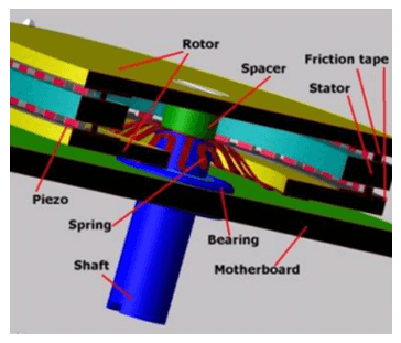
Figure 10 – Cross section of motor construction
The spring in the center of the upper rotor presses both rotors towards the stator. This force needs to be sufficient to ensure that there’s a good contact between the rotors and the piezo components on the stator perimeter. However, if it’s too strong it will act like a brake and block the motor.
Connecting the motor mechanically to the application should not disturb this balance. Ideally the mechanical design should ensure that the rotor only transfers rotational forces to the axle. A load of 75-150g mounted directly on the rotor will be OK, especially if the motor axle is vertical.
If the axle is horizontal, the mechanical load could make the rotors tilt whereby some of the piezo elements could lose contact with the rotors. This results in reduced motor performance and probably also increased acoustical noise level. Therefore, the load on horizontal axles should be lower and preferably mounted as close to the rotor as possible.
Resonances from the stator do have an impact of the rotor design, to avoid acoustical noise.
To achieve optimum friction properties, we recommend using our friction tape as an interface between the rotor and the stator. This will ensure the correct electrical insulation between the rotor and stator, motor performance and the lowest acoustical noise.
Rotor examples
Figures 11.1 to 11.5 (below) show various rotor examples with spring and encoder.

Figure 11.1 11.2 11.3 11.4 11.5 11.6 Rigid. Spring rotor. FR4 & steel spring. Rotor & Spring FR4. FR4 encoder. Rotor w/spring & encoder
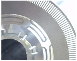
Figure 12 – Close-up of hollow shaft rotor.
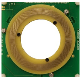
Figure 13 – 40mm hollow center rotor.
Hollow shaft and hollow center rotors
Figure 12 (right) shows an example of a 10mm hollow shaft rotor that fits to a 30mm stator. The rotor includes locking taps for a tight axle fit, steel springs and encoder markings around the perimeter.
A kit with this fitting is available in our E-Shop, based upon a 30mm motor.
Figure 13 (right), shows the principle for a maximum free hollow center. The rotor is made of FR4 and the kit also includes an encoder and spring blade.
A kit with this fitting is available in the shop with a free 40mm free center based upon a 60mm stator.
Rotors with lead screw
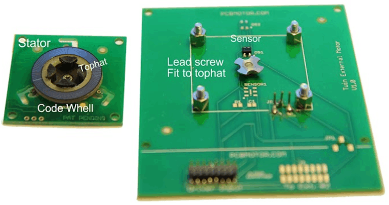
Figure 14 – Rotor and lead screw
Figure 14 shows and example of how a lead screw can be implemented with a PCBMotor.
Please note that the rotor includes the encoder and the top hat determines the stroke length of the lead screw.
A lead screw demonstration kit is available in the E-Shop.
The above rotor figures are just examples of various rotor solutions. PCBMotor’s mechanical design service can assist you moving from prototype development to (volume) production.


")


